Easy Mobile Phone Charger Circuit – A Home-Built Project
Are you looking for a simple way to build your own mobile phone charger? This beginner-friendly project demonstrates how to create a basic mobile phone charger circuit at home using only a few electronic components. It’s a great home-built project for electronics hobbyists, students, or anyone who wants to learn about how chargers work.
What is this project about?
In this project, you’ll build a mobile phone charger that converts AC (alternating current from your wall socket) to DC (direct current used by phones). This charger provides 5 volts, which is a common voltage for charging most mobile phones.
Why build this circuit?
It helps you learn basic electronics.
It’s a low-cost alternative to store-bought chargers.
It’s a good hands-on home-built project.
Know your circuit
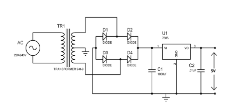
The simple Circuit Schematic of the charger is given below.
What You’ll Need: Parts:
Here are the main components used in this project:
Step-down transformer (230V to 9V) – Reduces the AC voltage from 230V to a safer level.
4 Diodes (1N4007) – Forms a bridge rectifier to change AC into DC.
Capacitor (1000µF, 25V) – Smoothens the DC output by removing ripples.
Voltage Regulator IC (7805) – Controls the output voltage and keeps it at a safe 5V.
Heat Sink – Keeps the voltage regulator cool.
PCB board / Breadboard – To mount your components.
Wires and Soldering Tools
Know the design:
How the Circuit Works:
Step 1: Voltage Conversion
The transformer takes 230V AC from your wall outlet and steps it down to 9V AC.Step 2: Rectification
The 4 diodes are connected in a bridge configuration to convert 9V AC into pulsating DC.Step 3: Smoothing
The 1000µF capacitor stores and releases energy to reduce voltage fluctuations and gives a more stable DC output.Step 4: Regulation
The 7805 voltage regulator IC takes the smoothed DC and ensures it stays at 5V, which is safe for charging most mobile phones.The output terminals for connecting your USB or mobile charging wire.
Know your construction:
Important Notes:
Safety First: Even though the output is low voltage, the transformer connects to 230V AC, which is dangerous. Be careful while handling.
Heat Dissipation: The 7805 IC may get hot, so it's good to attach a heat sink.
USB Output: You can connect a USB female socket to the 5V output to plug in your phone’s charging cable.
Advantages of This Project:
Simple design using easily available parts.
Useful for understanding how real chargers work.
It can charge low-power devices like feature phones or older smartphones.
Limitations:
This is not a fast charger.
It may not support newer smartphones that need more current (above 1A).
It doesn’t include advanced safety features like short-circuit protection or overcurrent protection.
Conclusion:
This mobile phone charger project is a great way to start learning electronics. It teaches you about voltage conversion, rectification, and voltage regulation – all important concepts in power electronics. With just a few parts and a bit of care, you can build your charger at home. Please give your valuable comments so that it can be improved to especially for beginners and novices in Electronics.


No comments:
Post a Comment